
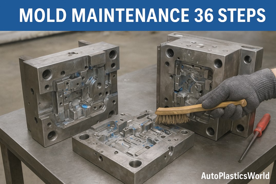
What is Mold Maintenance?
Mold maintenance refers to the systematic upkeep and care of molds used in manufacturing processes, such as injection molding, to ensure their optimal performance and longevity. It involves regular inspections, cleaning, lubrication, and repair to prevent defects, prolong mold life, and maintain product quality and consistency. Effective mold maintenance practices are crucial to minimize downtime, reduce production costs, and maximize overall efficiency in industrial manufacturing operations.
Why is Mold Maintenance Required?
Maintenance of molds is essential to preserve their functionality and productivity. Regular upkeep prevents mold damage, wear, and corrosion, ensuring consistent product quality and reducing production downtime. Neglecting maintenance can lead to defects, inconsistent output, and increased production costs. By inspecting, cleaning, and lubricating molds, potential issues can be identified and addressed promptly, extending their lifespan. Proper maintenance optimizes manufacturing efficiency, enhances mold performance, and ensures safe operations. Ultimately, mold maintenance is a cost-effective approach that safeguards investments, maintains high-quality production standards, and enables businesses to meet customer demands with minimal interruptions in their manufacturing processes. You can a separate article on mold maintenance, where I had to discuss types of mold maintenance in detail… read more
Mold Maintenance Process in 36 Steps
Mold maintenance involves a lot of activities that need to be performed accurately for better results. Here I provide mold maintenance in 36 steps with all necessary tools and procedures which are required to be followed if you are working on mold maintenance.
Before starting mold preventive maintenance, we make a checklist of mold preventive maintenance preparation. This checklist gives us an idea of what we will need to gather if we are going to begin mold maintenance. In this checklist, we mention the availability of certain mold-related data as prescribed for PM such as Mold Preventive Maintenance Plan, Mold History Card, Mold Daily Maintenance Checksheet, Last Sample Part, LPA Report, Mold Loading-Unloading Checksheet, Mold PM Checksheet, Mold Breakdown Summary Report, PPE and many more.
If you want to know how much time a mold need for a PM, the number of manpower requires for Mold PM, and at which frequency a Mold PM should be carried out, I have everything mentioned related to this in another article you can learn about this from here…. read more
Let’s jump to our main topic about Mold Maintenance: A Comprehensive Guide in 36 Steps –
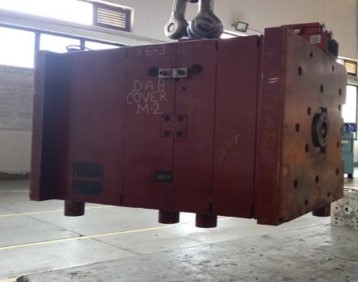
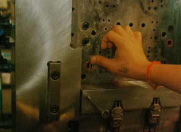
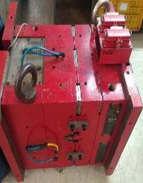
Step 1 – Bring The Mould To The Maintenance/Tool Room Area
- Take mold from the mold storage area to the maintenance/tool room area.
- Ensure the mold lock plate is available & bolting properly given to prevent mold opening while mold lifting before lifting mold from a mold storage area or from the machine.
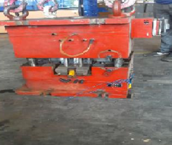
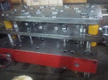
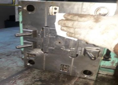
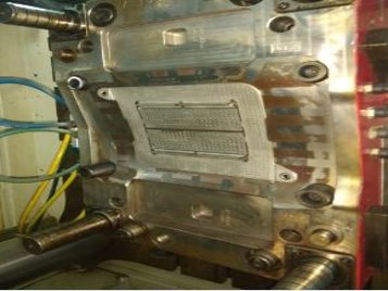
Step 2 – Place The Mould On Rubber Mat & Separate The Fixed Half From The Moving Half By Using Crane
- Ensure eyebolts are fully & securely tightened(Neck must seat).
- Four eye bolts must be used for separating the mold halves for balance lifting to prevent any accidents.
- Ensure the mold is not kept directly on the floor.
- Detach all lock plates before the mold separates into two halves.
- Ensure balance lifting.
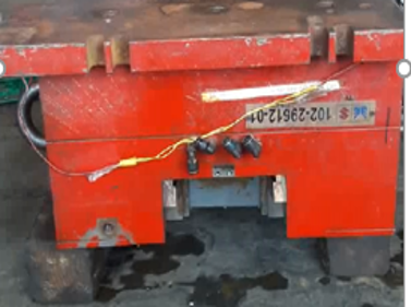
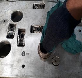
Step 3 – Keep The Mould Half On Rubber Mat/Wooden Block After Dismantle
- Ensure mold is kept over the wooden block, work table, or rubber Sheet after dismantling into two halves.
- Use a wooden block if needed for keeping the cavity half parallel to the floor.

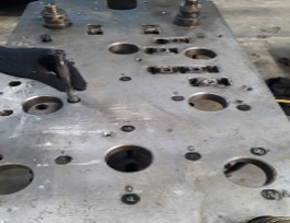
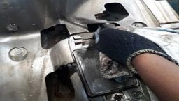
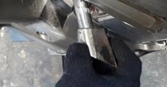
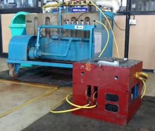
Step 4 – Start the Descaling Process for Cavity Half
- Start the descaling process of the cavity half. To learn more about the mold descaling process… read more
Step 5 – If Mould Having Hydraulic Ejector keep Jack at Ejector Stroke Area To Arrest The Movement
- Ensure sliders & weak section area should not touch the surface.
- While tilting the mold, ensure water connectors, hydraulic fitting, and other parts prone to damage. If yes protect them from damage.
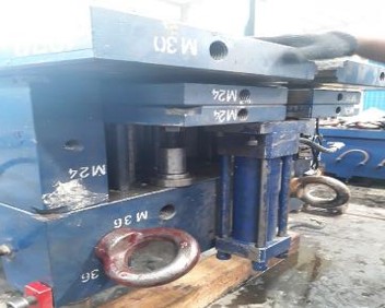
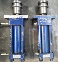
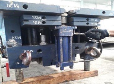
Step 6 – Remove The Hydraulic Cylinder (If Applicable)
- Ensure the identification marking on the hydraulic cylinder, if not available identify them.
- While removing the hydraulic cylinder, handle it carefully & keep it in a safe place.
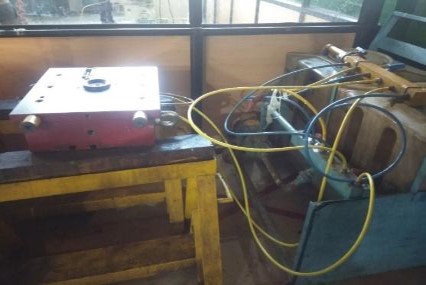
- Check leakage & movement of hydraulic cylinders by using a power pack.
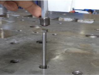
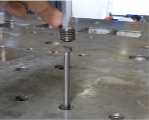
Step 7 – Remove All Sleeve Pins And Keep them At a Safe Location(If Applicable)
- Remove the grub screw from the bottom plate to remove sleeve pins (if applicable).
- Ensure sleeve pins have marked, if a mark not available then mark on sleeve pins & it’s position.
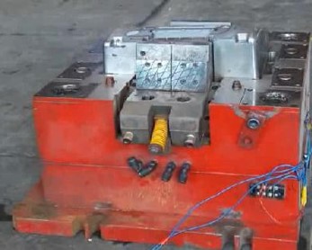
Step 8 – Remove The Moving Parts From Core Half (if applicable)
- Ensure the reference number marking on sliders.
- If the weight of the side core/moving slider/lifter is more than 8kgs, use the crane or take assistance.
- Remove the stopper bolt of the slider.
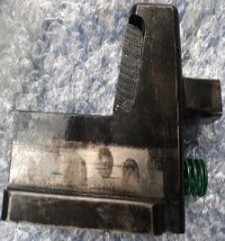
- Remove the slider spring (if applicable).
- Clean the sliding holes surfaces of guide rails.
Step 9 – Remove All The Lifter Cores From Moving Half (If Applicable)
- Ensure the identification marking on lifter cores.
- While removing the lifter cores, ensure the bolts/washers are screwed on the same shaft.
- While removing the lifter cores, ensure the dowels not falling.
- While removing lifter cores be aware of the sharp corners of lifter cores, handle them carefully & keep them in a safe place.
Step 10 – Remove The Allen Bolts And Separate Bottom Plate & Spacer From Moving Half
- Ensure the water/hydraulic pipes are removed from the spacer block.
- Ensure the wires of the limit switch/sensor are disconnected from the spacer (if any).
- Be aware of oil/water spillage when disconnecting the water/oil pipes.
Step 11 – Dismantle The Ejector Plate & Ejector Retainer Plate
- Remove the ejector back plate Allen bolt with the help of a pneumatic wrench & keep all bolts in a safe place.
- If bolt hex. head in damaged condition uses the Allen key to remove the bolt and use a new bolt instead of it during mold assembly time.
- Remove the ejector back plate after removing the bolts.
Step 12 – Remove All Ejector Pins, Sleeves, Ejector Blades, Ejector Pads, Ejector Retainer Plate
- Check & confirm the identification mark on all ejector assembly parts, if you working on mold maintenance
- Check for any tight fitment/movement of ejector parts (to be corrected after cleaning the hole).
- Check for any bend of ejector pins.
- Check for any plastic material leakage in the ejector pin/blade/sprue puller hole (to be cleared).
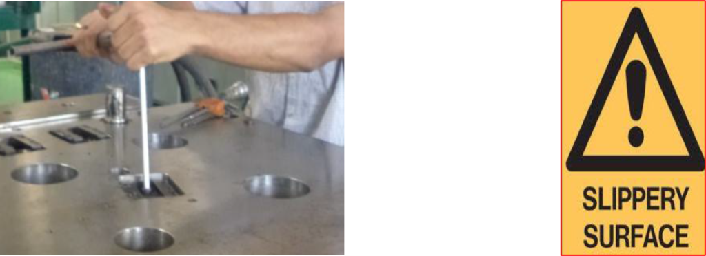
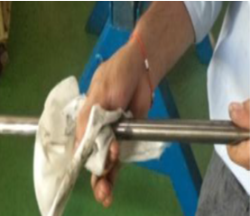
Step 13 – Clean All The Ejector Pins, Sleeves, Blades, Return Pins & Lifter Rod
- Check the scoring mark on ejector parts (replace with a new one if found damaged).
- Clean all the dust & rust from ejector parts for effective mold maintenance.
- Check for bolt tightness in guide blocks for lifters’ cores shafts.
- Always wear hand gloves while cleaning any parts having grease, rust, or dust on them.
Step 14 – Remove Core Insert (if applicable)
- Ensure inserts are kept on nylon pads/plastic bins/rubber pads to avoid damage during mold maintenance.
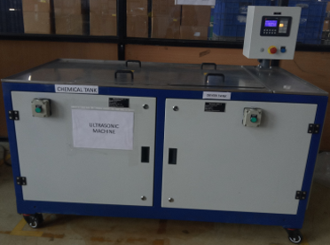
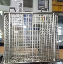
Step 15 – Ultrasonic Cleaning Machine (Clean Core Insert, Child & Sliding Parts
- Place the core inserts, child & sliding parts in the bin of the chemical tank of the ultrasonic machine for cleaning.
- Remove the part from the chemical tank and place it in the bin of the dryer tank for cleaning the chemical part.
- We had write a separate article on ultrasonic cleaning machines for mold maintenance you should read about it.
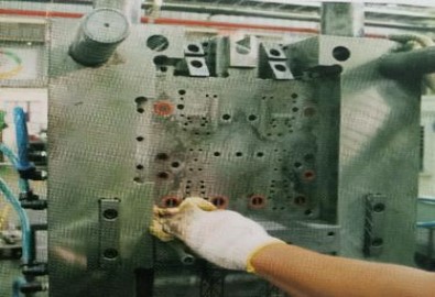
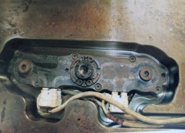
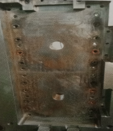
Step 16 – Cleaning of Core Half(All Ejector Pin Holes)
- Check scoring & rust marks in ejector holes.
- Check material leakage in ejector pins/sprue puller hole of core half.
- Remove the gas deposition from holes by cleaning and flowing air.
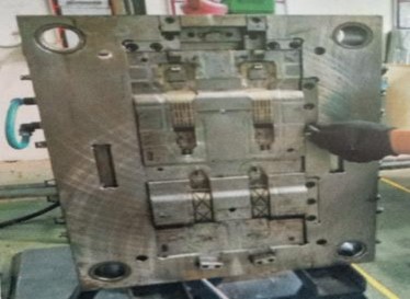
Step 17 – Remove all O-Rings & Clean Core Plate, Sliding Surface, Air Vents & Ensure no Damage in Parting Line & Core Profiles
- Ensure no rust, damage, or bulging on the surface, in guide rails & parting line.
Step 18 – Check & Clean Guide Pillar
- Ensure no scoring, rusting, bend, or loose fitment in the guide pillar during mold maintenance activity.
Step 19 – Apply Grease ( High-Temperature Resistance ), Put New O-Rings & Assemble The Insert
- Ensure all O- Rings are assembled.
Step 20 – Assembly Lifters On Their Location By Applying Grease
- Clean all the pocket areas properly and ensure the spring washer is used after Allen bolts while lifter assembly.
- Ensure dowel fitment is not loose.
- Ensure free movement of guide rails.
- Ensure the bolt condition is good and the correct length.
- Be careful from the sharp edges of the lifter and don’t forget to wear hand gloves while lifter assembly.
Step 21 – Assemble The Ejector Plate & Ejector Retainer Plate With Ejector Pin
- Ensure all the ejector pins are at their location as per the identification mark after lubricating with grease during mold maintenance.

Step 22 – Assemble The Back Plate, Spacer Blocks & Tight The Allen Bolt
- Ensure the bolt condition at the hex. head and thread area is not damaged, if found damaged change with a new one.
Step 23 – Assembly The Hydraulic Cylinder, Tight The Mounting Bolts & Oil Pipes (If Applicable)
- Ensure the hydraulic hose pipes are connected.
- Ensure the hydraulic cylinder shaft is fully tight with a nut arrangement.
- Ensure the bolt condition at the hex. head area and thread.
- Ensure the wire of the limit switch/sensor is connected (if any).
Step 24 – Place the Sleeve Pins & Tight The Grub Screw at the bottom plate (if applicable)
- Ensure the identification mark of the ejector sleeve pin location & ejector Sleeve pin during pin fitting.
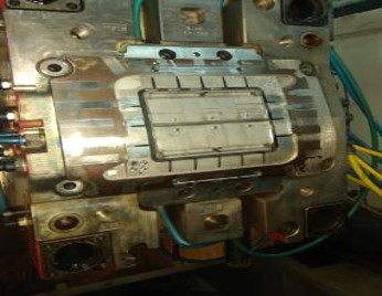
Step 25 – Invert The Core Half After Assembly Completed
- Ensure no wrong assembly.
- While tilting the mold, ensure all connectors, prone to damage, if yes protect them from damage.
- Check the ejector parts level on the core surface.
- Ensure all the connection is restored after core half mold maintenance done.
Step 26 – Assemble Moving Parts (Sliders/Side Core) if applicable
- Apply lubricant to the sliding surface, assemble the slider, and tightened the stopper bolt properly (if applicable).
- Ensure the spring is not broken and has no scoring mark on the sliding surface.
- Ensure no guide rail bolts are broken/missing.
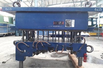
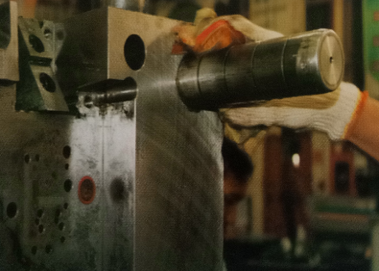
Step 27 – Start Descaling In Core Half After Cavity Half Descaling Completed
- Remove the cavity half from the descaling machine after the descaling of the cavity half is completed.
- Ensure no water leakage from loop pipe/fittings.
- Check and match the LPM of the mold with its standard value after descaling, and take corrective action if the standard value is not achieved.
- After cavity half descaling is done, start core half descaling.
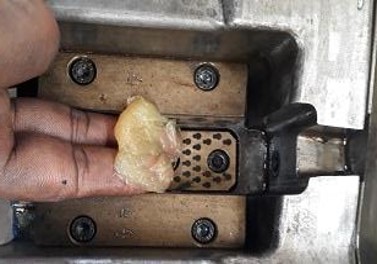
Step 28 – Check Hot Runner (If Applicable)
- Ensure no plastic material leakage from the hot runner manifold.
- In case of leakage is observed, dismantling & repair of the hot runner system must be conducted after consulting with the hot runner supplier.
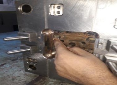
Step 29 – Remove Cavity Insert/Slider/Hydraulic Cylinder (If Applicable)
- Be careful of etching the surface(if applicable).
Step 30 – Remove the O-Ring, Clean the Cavity Plate, Sliding Surface, and Air Vents & Ensure no Damage in the Parting line surface & Cavity Profile (if any)
- Ensure no rust, damage, or bulging on the surface & no blockage of air vents.
Step 31 – Cleaning of Slider/Insert Surface & Air Vents & Ensure no Damage in Parting Line & Cavity Profiles
- Ensure no rust, scoring, bend, or damage at the cavity insert.
- If rust & dent are observed in the etching area, it is recommended to consult with etching repairing vendors.
Step 32 – Ultrasonic Cleaning Machine (Clean Cavity Insert, Child & Sliding Parts) if applicable
- Place the cavity inserts, child & sliding parts in the bin of the chemical tank of the ultrasonic machine for cleaning.
- Remove the part from the chemical tank and place it in the dryer tank’s bin for cleaning the chemical part.
- Remove the part from the dryer tank of the ultrasonic cleaning machine, after the part dries out.
Step 33 – Apply Grease in Cavity Half & Insert O-Rings & Assemble The Insert in The Mould
- Ensure no rust, bulge & burr on the parting line & cavity profile.
- Ensure all O-Rings are assembled.
Step 34 – Stop Descaling Machine After Descaling Completed in Core Half
- Remove the core half from the descaling machine after the descaling of the core half is completed & to check effective descaling follow the same process as followed for the cavity half in Step 27.

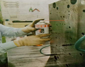
Step 35 – Use Anti-Rust Spray on Cavity & Core Part Area Before Closing The Mould
- Ensure all the pins are placed at their location as per identification marking.
- Use the anti-rust spray on the part area of the core and cavity before mold closing.
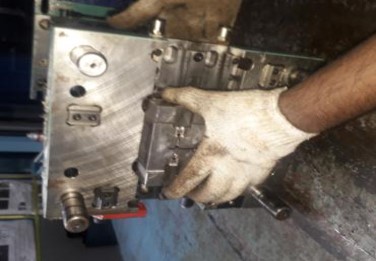
Step 36 – Assemble The Both Halves, Tightened The Lock Plate & Keep The Mould Vertically
- Tight the lock plate properly before lifting the mold.
- After mold preventive maintenance is done place the mold in its defined location.
- Fill & update all the documents related to mold preventive maintenance.
Thank you for sharing excellent informations. Your website is very cool. I am impressed by the details that you have on this website. It reveals how nicely you perceive this subject. Bookmarked this web page, will come back for extra articles. You, my friend, ROCK! I found just the info I already searched all over the place and just couldn’t come across. What a perfect web site.
I got what you mean ,saved to fav, very nice site.
This is really attention-grabbing, You are an overly skilled blogger. I’ve joined your feed and stay up for seeking more of your fantastic post. Additionally, I’ve shared your site in my social networks!
You need to take part in a contest for top-of-the-line blogs on the web. I’ll suggest this site!
I’m not that much of a online reader to be honest but your sites really nice, keep it up! I’ll go ahead and bookmark your website to come back later on. All the best
Super helpful
I was very pleased to find this web-site.I wanted to thanks for your time for this wonderful read!! I definitely enjoying every little bit of it and I have you bookmarked to check out new stuff you blog post.
Quality analysis
Its like you learn my thoughts! You seem to grasp so much approximately this, such as you wrote the e-book in it or something. I believe that you just can do with a few to drive the message house a little bit, but other than that, that is great blog. A great read. I’ll definitely be back.